Here is a link to the STL files for our CAD.
https://drive.google.com/folderview?id=0BzH0B2Rs0kPGX2VSQWtEWDA4RmM&usp=sharing
Thursday, October 23, 2014
Monday, October 20, 2014
Estimate Machining & Optimization Times
Last week we machined out first mold. Looking ahead, below are our expected machining times for all our molds. After machining our molds, we will begin injection molding and process optimizations and have included estimates for that below too.
Machine Time Estimate for Lathe and Mill
Once our molds are made in Solidworks, we import them to Mastercam where we plan out what machines and tools we will use to make them. Mastercam is sync with the 2.008 Mill and CNC Lathe and thus gives us estimates for machining times on both machines.
Part
|
Lathe Time
|
Mill Time
|
Yoyo Body Cavity
|
7 min 9 sec
|
0
|
Yoyo Body Core
|
6 min 29 sec
|
1 min 30 sec
|
YYB w/Spin Stick Core
|
6 min 29 sec
|
6 min 24 sec
|
Retaining Ring Core
|
2 min 39 sec
|
3 min 13 sec
|
Retaining Ring Cavity
|
35 sec
|
0
|
Thermoform
|
3 min 12 sec
|
54 seconds
|
Letter Mold Core
|
0
|
25 min
|
Letter Mold Cavity
|
0
|
1 hr 30 min
|
Gold Board Mold Core
|
0
|
30 min
|
Gold Board Mold Cavity
|
0
|
9 min 21 sec
|
Entire Wheel of fortune board Mold Core
|
1 min 1 sec
|
1 hr 5 min 27 sec**
|
Entire Wheel of fortune board Mold Cavity
|
3 min 37 sec
|
1 hr 16 min 40 sec**
|
Projected Timeline
Process Optimization
|
October 20th - November 10th
|
Make Final Parts
|
November 10th -November 24th
|
Assembly
|
November 24th - Dec 5th
|
Previously we planned on having all our molds made last week. However, due to longer machine times than expected and how quick machines get booked up, we have shifted our first injection molding iteration back by a week and will have to shorten our optimization and final production run time. (this is reflected also in our Gantt Chart).
Projected Process Optimization Time
To optimize our process we will run iterations of injection molding parts, measuring parts for accuracy, and re-designing as needed. To get an estimate of how long this process will take we have estimated the time of these iterations.
Injection Molding time is dominated by cooling time. From class lecture, we learned that cooling time can take upwards of half of the entire injection molding process. Cooling time for our parts can be derived from the equation Cooling Time=(thickness of part)^2/alpha, where alpha is the thermal diffusivity of the material. Our yoyos will be made from polypropylene with a thermal diffusivity of 0.096mm^2/s. Our parts have an average thickness of ~2.54mm, thus the average cooling time is about 67 seconds. To make 10 parts will thus take us about 20 minutes. For all our parts it will take us ~110 minutes (we have already booked 3 hours of IM time so we'll have our first iteration of all parts done this week!). Thermoforming each part also takes us about a minute, adding 20 minutes to our total estimate.
At worse we expect to have to re-machine all our molds and injections mold again. Our total machine time is about 5.5 hours. So our total process optimization time is roughly 16 hours of lab time plus the time to re-CAD any changes. We believe 3 weeks should be sufficient time to get this done between the five of us.
Friday, October 17, 2014
Manufactured Mold: Thermoform
We made our first mold in lab today, using the CNC lathe, mill, drill press, arbor press, and reamer!
The thermoform part only involves one mold, shown below:
We used the lathe to turn the dome shape and ledges, while we used the mill, drill press, and reamer to create the two pin holes. Another drill press was used to create eight tiny vacuum holes, while an arbor press pushed the pins into the mold.
We also scheduled time to do a couple of test runs -- we made five test covers in all:
As expected, our first run didn't result in perfect yoyo covers off the bat. The texture was speckled (dust!!!), and there was some webbing near the pins.
Thus, for the subsequent runs, we pushed the pins down more to decrease webbing, cleaned the mold and plastic extra well to decrease chances of catching dust, and altered some parameters such as heating time.
Next week, we plan to manufacture the rest of our yoyo part molds, and start injection molding!
The thermoform part only involves one mold, shown below:
 |
| The top of our thermoform piece mold, with the dome structure that will form our clear plastic yoyo cover. |
 |
| The bottom of our thermoform piece mold, with the pin holes at the north and south axes. The vacuum holes are visible right next to the inner ledge. |
We used the lathe to turn the dome shape and ledges, while we used the mill, drill press, and reamer to create the two pin holes. Another drill press was used to create eight tiny vacuum holes, while an arbor press pushed the pins into the mold.
 |
| A tiny drill was used to create the vacuum holes. |
 |
| The arbor press right before we pushed the pins down into the mold. |
 |
| The top face of our very first thermoformed part. |
 |
| The bottom face of the yoyo cover. |
Thus, for the subsequent runs, we pushed the pins down more to decrease webbing, cleaned the mold and plastic extra well to decrease chances of catching dust, and altered some parameters such as heating time.
Next week, we plan to manufacture the rest of our yoyo part molds, and start injection molding!
Preliminary Mold Design: Retaining Ring
This week, we've been finishing up designing our yoyo part molds in preparation for our first test run! We have one mold for the thermoformed clear plastic cover, and two each (a cavity and core) for the yoyo body, retaining ring, lettering, gold board, and entire wheel of fortune board.
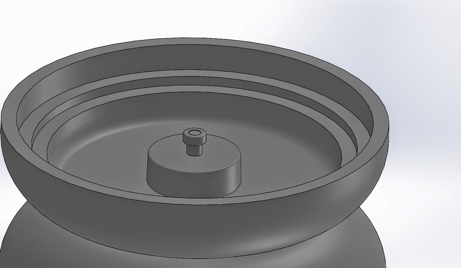
One of the molds ready for its first run is the retaining ring:
This part sits on top of the first ledge of the yoyo body, keeping the thermoformed cover in place, which will itself sit on the second ledge of the yoyo body.
The mold was created in SolidWorks using its Mold Design tools. The parting line was chosen in the middle of the ring's larger diameter to facilitate easy removal, and a shut-off surface was created at the bottom of the ring's smaller diameter.
The part was scaled by 1.02 based on shrinkage calculations from previous production runs of a similar retaining ring in past classes. The average outer ring diameter size was 1.9415" for this past ring, while the mold diameter itself was 1.98."
The mold drawing was then transferred to Mastercam to add the runner and ejector pin hole placements:
Since our retaining ring includes fillets which we didn't want the ejector pins to dent when removing our part, we decided to place the ejector pin holes outside of the part and create runners to the ring. (We had to use the largest radius ejector pin holes available since our yoyo body was already at the maximum size of 2.5" in diameter.)
In addition, we decided to place the ejector pin holes on the mold core instead of the cavity (where they typically are) to work around the fillet issue.
To manufacture these molds, we plan to first use the CNC Lathe, then the ProtoTRAK Mill. We chose the tools that would fit and provide the best finishes:
Here's to hoping for a successful first test run!
One of the molds ready for its first run is the retaining ring:
 |
| Both the core (bottom) and cavity (top) molds. |
 |
| The core mold features a filleted pocket around the boss extrude. |
 |
| The cavity mold is stepped for the ring's ledges. |
The mold was created in SolidWorks using its Mold Design tools. The parting line was chosen in the middle of the ring's larger diameter to facilitate easy removal, and a shut-off surface was created at the bottom of the ring's smaller diameter.
 |
| A view of the parting line feature in SolidWorks. The body shown is our retaining ring. |
 |
| The retaining ring cavity mold we based our shrinkage calculations on. |
 |
| CNC Lathe Mastercam for the cavity mold. |
 |
| CNC Lathe Mastercam for the core mold. |
 |
| ProtoTRAK Mill Mastercam for the core mold. |
In addition, we decided to place the ejector pin holes on the mold core instead of the cavity (where they typically are) to work around the fillet issue.
To manufacture these molds, we plan to first use the CNC Lathe, then the ProtoTRAK Mill. We chose the tools that would fit and provide the best finishes:
Retaining Ring Core:
Step
|
Operation
|
Machine
|
Tool
|
Justification
|
1
|
Rough Cut
|
Lathe
|
T0303
|
Used Tool 3 because we wanted to cut the outside diameter.
|
2
|
Finish Cut
|
Lathe
|
T0303
|
Used Tool 3 to finish to keep it consistent with the rough cut.
|
3
|
Groove
|
Lathe
|
T0909
|
Chose Tool 9 as a trepanning tool in order to cut a groove.
|
4
|
Center Drill
|
Mill
|
3/16” Center Drill (#2)
|
Chose the only appropriate tool to center drill the ejector pin holes first.
|
5
|
Peck Drill
|
Mill
|
0.120” Drill (#31)
|
Chose the only appropriate tool to create the ejector pin holes.
|
6
|
Contour
|
Mill
|
⅛” Ball End Mill
|
Chose a ball end mill tool to make one of the runners from the ejector pin holes.
|
7
|
Contour
|
Mill
|
⅛” Ball End Mill
|
Chose the same ball end mill tool to make the sprue runner and the other ejector pin runner.
|
Retaining Ring Cavity:
Step
|
Operation
|
Machine
|
Tool
|
Justification
|
1
|
Rough Cut
|
Lathe
|
T1010
|
Chose Tool 10 because we needed to bore out the cavity.
|
2
|
Finish Cut
|
Lathe
|
T505
|
Chose Tool 5 to finish because it has a smaller radius.
|
Here's to hoping for a successful first test run!
Monday, October 6, 2014
Yo-Yo Design!
Yo-Yo Design:
We designed our yo-yo around the Wheel of Fortune - hence our team name! Here are a few pictures of our yo-yo
Looking at the exploded view of our yo-yo above, we can explain all the parts. Starting from the top piece:
1. Retaining Ring (Injection Mold) - This piece is press-fit into the yo-yo body and keeps the thermoformed cover in place.
2. Yo-yo Cover (Thermoform) - This piece is thermoformed, cut on a die, and placed on a ledge on the yo-yo body.
3. Press Ring (Lasercut) - The press ring sits on the spin-stick, and it keeps the wheel of fortune from popping off. It is press fit on top of the spin stick. The picture below shows the spin stick and press ring. The wheel of fortune would go in the space in between to spin.
4. Wheel of Fortune (Lasercut) - The wheel of fortune spins between the spin stick and press ring. The wheel consists of a lasercut disk, on which a sticker of the wheel of fortune is placed.
5. Spin Stick (Injection Mold) - picture below. This piece is injection molded, The spin stick is pres fit into the yo-yo body.
6. Yo-Yo Body (Injection Mold) - the body contains a place for press-fitting the spin stick and a ledge for press-fitting the back piece and the Retaining Ring.
7. Attachment between Yo-yo- bodies : This consists of the screw that wholes the two body pieces together
8. Yo-Yo Body (Injection Mold) - 2nd piece
9. Back Piece (Injection Mold + Overmolding) - This piece is overmolded, featuring different colors to write out the words "Wheel of Fortune"
10. Yo-yo Cover (Thermoform) - 2nd piece
11. Retaining Ring (Injection Mold) - 2nd piece
We incorporated principles of design for manufacturing into the features of the parts:
Table of Specs: A table of specifications for the Yo-yo design was made, with critical dimensions of the components and assembly. It can be found here.

Gantt Chart: We also created a Gantt Chart to schedule the design and manufacturing of our yoyo. You can see the chart here.

We designed our yo-yo around the Wheel of Fortune - hence our team name! Here are a few pictures of our yo-yo
 |
| Back Face of the Yo-yo has the name of our yo-yo, in the letter format of its namesake gameshow |
 |
| Side View |
 |
| Front Face of Yo-yo contains a spinning disk that will look like the Wheel. The image of the wheel will be printed on a sticker |
 |
| Exploded View |
1. Retaining Ring (Injection Mold) - This piece is press-fit into the yo-yo body and keeps the thermoformed cover in place.
 |
| Retaining Ring, Pressfit into yo-yo body |
2. Yo-yo Cover (Thermoform) - This piece is thermoformed, cut on a die, and placed on a ledge on the yo-yo body.
3. Press Ring (Lasercut) - The press ring sits on the spin-stick, and it keeps the wheel of fortune from popping off. It is press fit on top of the spin stick. The picture below shows the spin stick and press ring. The wheel of fortune would go in the space in between to spin.
 |
| Picture of Spin Stick and Press Ring |
4. Wheel of Fortune (Lasercut) - The wheel of fortune spins between the spin stick and press ring. The wheel consists of a lasercut disk, on which a sticker of the wheel of fortune is placed.
5. Spin Stick (Injection Mold) - picture below. This piece is injection molded, The spin stick is pres fit into the yo-yo body.
 |
| Spin Stick |
6. Yo-Yo Body (Injection Mold) - the body contains a place for press-fitting the spin stick and a ledge for press-fitting the back piece and the Retaining Ring.
 |
| Yo-yo Body |
7. Attachment between Yo-yo- bodies : This consists of the screw that wholes the two body pieces together
8. Yo-Yo Body (Injection Mold) - 2nd piece
9. Back Piece (Injection Mold + Overmolding) - This piece is overmolded, featuring different colors to write out the words "Wheel of Fortune"
10. Yo-yo Cover (Thermoform) - 2nd piece
11. Retaining Ring (Injection Mold) - 2nd piece
We incorporated principles of design for manufacturing into the features of the parts:
- In the CAD model of the injection molded pieces, we put fillets on the sharp edges, to make sure that the part slides out easier
- We put draft angles of 1 degree on the sides of the yo-yo body to ensure that the injection molded part doesn't get stick
- We incorporated press-fits into our design and ensured that only the sides of those press-fitted pieces were 90 degrees
Table of Specs: A table of specifications for the Yo-yo design was made, with critical dimensions of the components and assembly. It can be found here.
Gantt Chart: We also created a Gantt Chart to schedule the design and manufacturing of our yoyo. You can see the chart here.
Subscribe to:
Posts (Atom)