Wednesday, December 10, 2014

Video, Cost Analysis, and Recommendations


We FINISHED!!! Here is a video of all that we've done this semester! Check it out to see our process from beginning to end.

Summary of our cost analysis for prototyping vs. manufacturing:

Yoyo cost contributors are broken down into fixed and variable costs. Fixed costs don’t scale directly with production and include yoyo design and mold machining time. As we have a relatively short run of parts, molds aren’t consumable. Other costs scale with the yoyo, such as raw materials, injection molding overhead, thermoform overhead, and labor. Factoring in everything for our final run of 50 yoyos, each cost about $86 counting in student hours, design, machine and manufacturing time, and materials. Because the per-yoyo overhead is very small compared to fixed costs, manufacturing at larger scales would radically decrease the yoyo’s total cost.

How our YY design was adapted to meet the constraints of the 2.008 manufacturing
equipment, and how you would change it for mass production:


Lasercut Wheel: For mass production, the laser-cut wheel would be injection molded (or extruded and then cut), as the lasercutting process has a higher cost and a lower rate of production.

Wheel of Fortune Overmolded Board: For our assembly, we decided to overmold as a challenge, since we heard it was difficult (and it was). For mass production, however, we would recommend using stickers instead since overmolding is time-consuming and difficult to optimize.


Our team’s recommendations for improvement of the 2.008 class:


  • We greatly enjoyed the team project portion of the class! It was a well-designed lab that brought together many different features of the manufacturing process together - CAD (and design), machining, injection molding, thermoforming, and key features on design for manufacturing, design for assembly, and the optimization processes. It was also relatively easy to divide up all the parts to individual team mates, and debugging processes are made easier with multiple people. Dave and David also do a wonderful job of helping us solve problems with our molds and production.
  • The spacing of yoyo deliverables clumped around the beginning and end of the semester, with few assignments in the middle. While the earlier deliverables occur week after week, there is a period in the middle of the term when we are working on optimizing our molds and runs but the deliverables were minimal. It would be optimal to evenly distribute this work somehow – perhaps the production of all molds should be finished by a certain date, or the production of 1 yo-yo should be completed before Milestone 11.
  • While we agree that there should be some individual portion to 2.008, many of the homework problems were difficult to do on our own and there is much value in learning from our peers when psetting. Possible having some other way of measuring our individual understanding of the material, while preserving the opportunity to learn from others through psets would work better.
  • Unfortunately, we had three lab groups in our section, and since most machining time could only be booked during our lab sections, this meant that, especially at the beginning when machining the first molds, there was a line for machining during our lab time, a problem that other lab group did not experience. Perhaps having a designated machine shop time for groups with 3 lab sections may be useful.
  • The CAD/CAM labs were great for learning Mastercam! Though, we would have liked to see less depth covered in lab time, as it is a lot of information presented at once. Having the information available somewhere where we can access it at any time (like youtube tutorials or written tutorials in the course locker) would be really helpful when working on our molds outside of lab time. Comprehensive written tutorials for Mastercam would eliminate the need to do tutorials during lab time, thus lab time could serve as an office hours for Mastercam.
  • During class lecture it would be wonderful to have more of the information that is verbally articulated also written on the slides (or possible on the handouts have extra notes). Some slides just have equations or pictures with little explanation written, so if I did not understand it well enough when it was said during lecture to write good notes, it would be hard to get the information later. Summary slides of key points through out the lecture would also help to solidify my understanding.
From all of us here on the Wheel of Fortune 2.008 team, we want to say thank you for following our progress!


Best,
Melody, Kath, Melanie, Skyler, and Alexxis

Friday, December 5, 2014

Production Runs Finished!

This week, we've finished up assembling our yoyo's! All of our productions runs were finished last week, but we needed a bit more time to order the stickers and assemble everything.

Here's a look back at everything:

Thermoform:

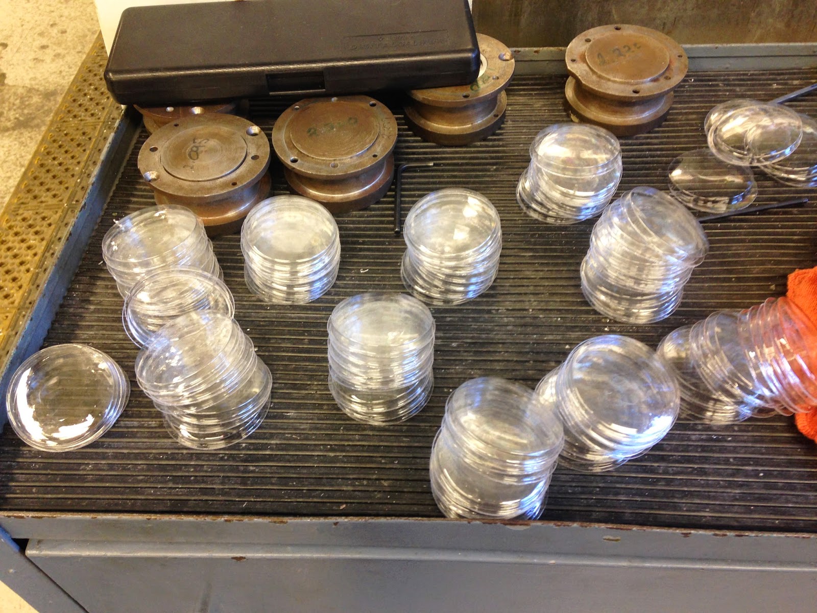
Here is a picture of the thermoformed cover. Right after thermoforming, the piece looks like as below.


The piece is subsequently cut to yield the clear covers that will fit in the yo-yo body.


Key features: The key features are the diameter of the dome, the height of the dome, and the outside cut diameter. The diameter of the dome is determined by the webbing between the pins and the dome, because webbing increases the diameter, and the dome may not be able to fit inside the retaining ring. The outside cut diameter depends on the die used to cut the covers from the thermoformed sheet. It also depends on the protrusion of the pins, which align the cutting die - if there is too much webbing, the pins will not be substantial enough to align the piece to the cutting die. Thus, the amount of webbing is a key feature that determines the quality of the piece.


Successes: We were able to decrease the webbing between the dome and the pins by increasing the heat time and oven temperature. This, however, caused a longer production time, from the increased heating and cooling times, but the quality of the piece was much improved. In our disturbance, we introduced shorter heating times, and the introduction of more webbing caused an increase in the diameter of the dome. This is seen below in the figure.


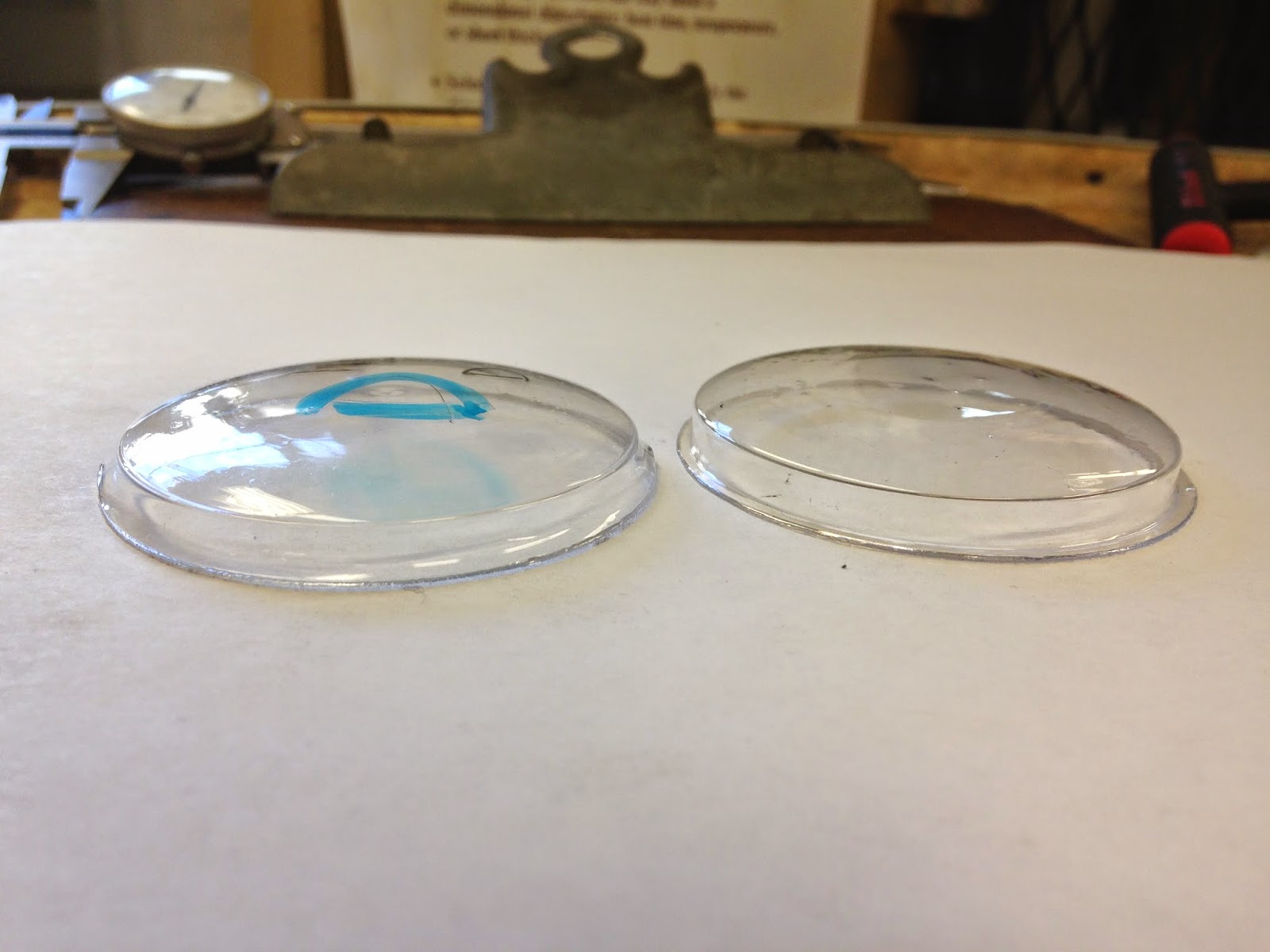
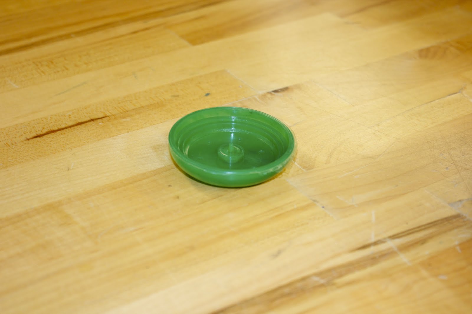
This is one of the "disturbance" thermoformed pieces, which has a shorter heating time. As a result, there is more webbing. When it is cut out, the diameter is much larger and the height of the dome is decreased. This is seen below.


This is a comparison of the distaurbance thermoformed piece (on the left) and the regular theormoformed piece. The disturbance piece has an obviously larger dome diameter and a less defined corner, which would cause fitting problems.
We successfully reduced webbing by increasing oven temperatures.


Opportunities for improvement: Currently, some of the pieces are speckled with bumps caused by dust particles which adhered to the clear particles while the plastic was heated and thermoformed. Although precautions were taken in cleaning the mold and blowing dust off the plastic, this did not improve the quality, and dust continued to stick to the plastic from the static when the plastic was peeled. One good improvement would be to increase the quality of the piece by getting rid of the dust.
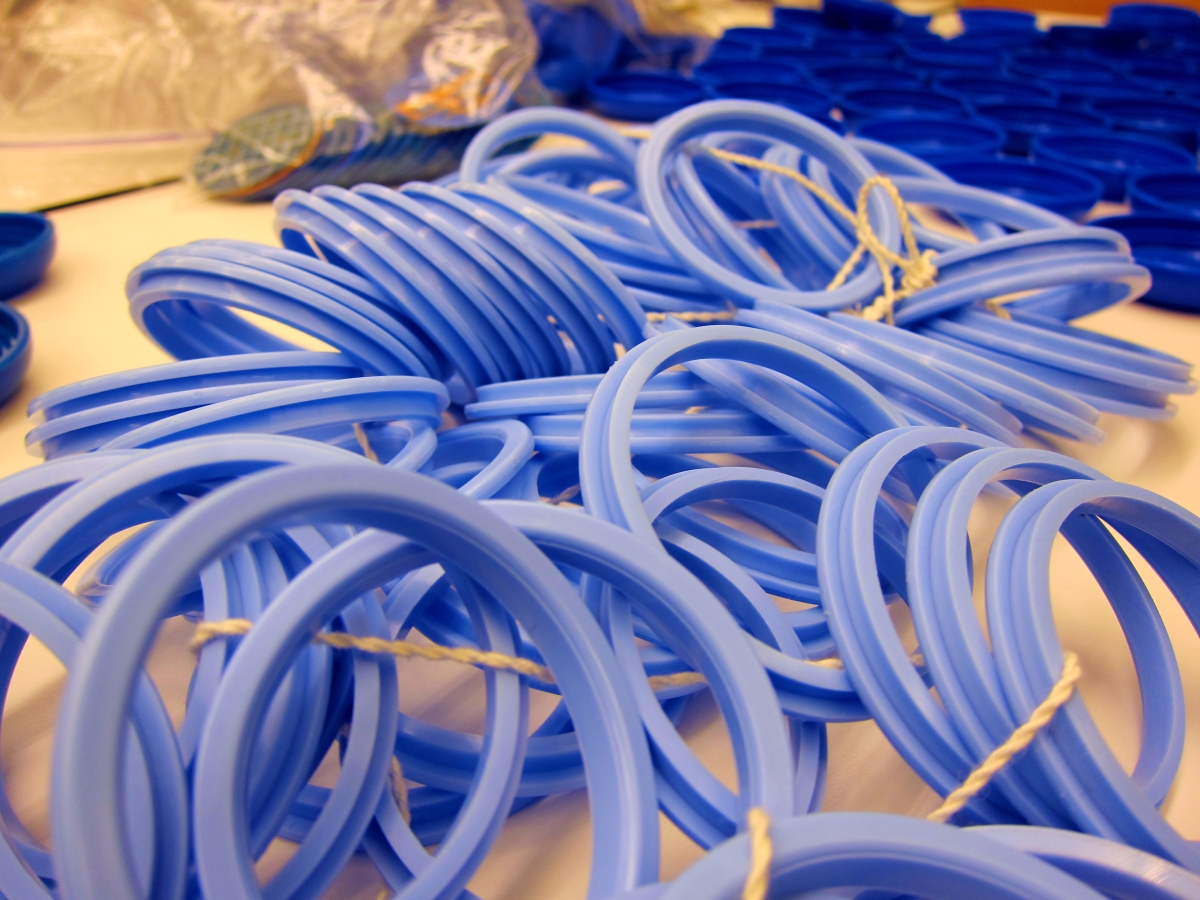

Retaining Ring:


Optimized-IMG_2629_edited.jpg


Key features:


The most important dimensions of the retaining ring are the snap fit diameter (the inner diameter) and the width of the snap fit. If the two did not match the yoyo body’s, the process would need to be changed and the retaining ring redone.


Successes:


Luckily for us, the final retaining ring did fit perfectly into each of the yoyo bodies, and even gave a satisfying snap each time during assembly! However, it took several tries to get there.


We initially had issues with the retaining ring not coming cleanly off of the molds when the ejector pins tried to push the part off. After changing everything from the pressure profile to the cooling time, it was determined that the mold would have to be remachined since the gates were just not strong enough (read: too thin) to help push the part off.


Unfortunately, the gates could not simply be made deeper because they were already on the cusp of cutting too deeply into the retaining ring pocket. Instead, we decided to drill an outer ring, allowing us to add the maximum number of gates possible.


IMG_2057.JPG


IMG_2129.JPG


Once the part was consistently ejecting from the molds, the pressure profile was tweaked until we eliminated flash!


IMG_2149.JPG


Opportunities for Improvement:


Ideally, we wouldn’t have had to snip the gates off of every retaining ring before the final assembly -- not just in the interest of time, but in terms of aesthetics as well. Even the best-snipped ring still had visible blemish marks if you look closely enough.
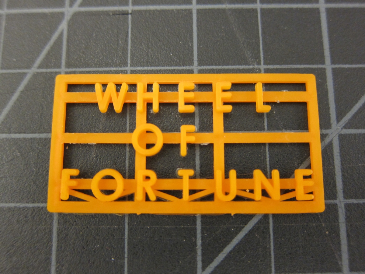

Letter Board


2014-11-25 16.10.05.jpg


Key Features:
This part was mostly for aesthetics thus there are no critical dimensions. However, important features include the look of the letters, filling the mold properly, and pinching the molded parts well.
Successes:
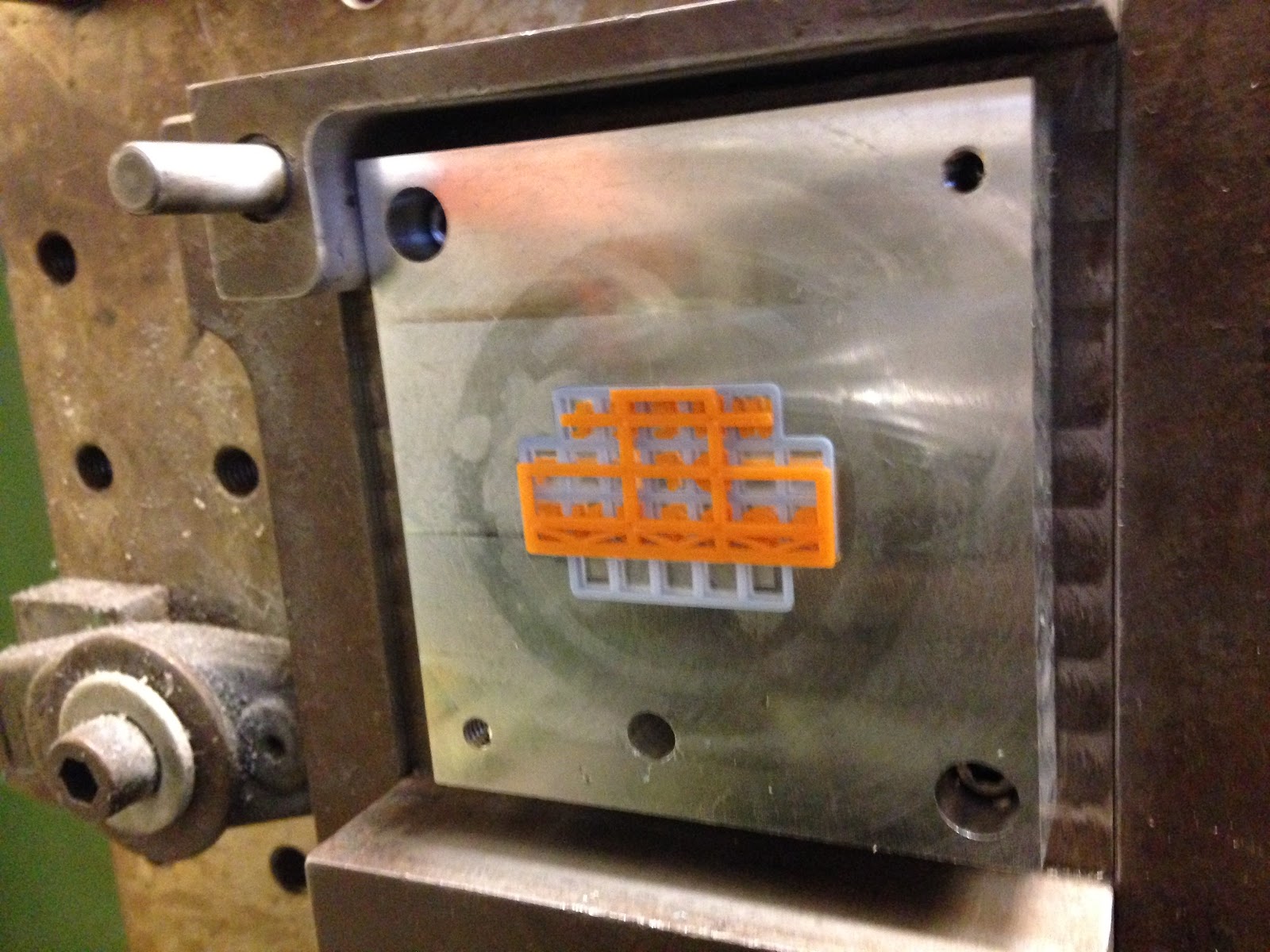
The letters went through several iterations before they were ready for final production. Initially the letters were at a height of 0.083 inches, however, releasing these parts from the mold was difficult even with the use of a mold-releasing spray and ejector pins. Thus the part was reduced to 0.05 inches in height. This change combined with ejector pins and mold-releasing spray made it possible to run these parts in fully automatic during final production.


Optimized-IMG_2547.JPG


Optimized-IMG_2592.JPG


The board initially had filling problems. The channels were only 0.025inches in height and thus impeded the plastic flow from filling the mold. Simply increasing the channels to 0.05inches allowed for easy fill.


In the final mold we were able to control the filling of the mold and pinching of the parts well as to minimize parts moving and keep the plastic injected into the last mold from covering up the board and letters but still fill them properly. This took many iterations of optimizations which included better orientating the gates on the final mold and adding reinforcements to the letters so they would not move as much in the final mold.
2014-11-25 15.59.31.jpg
Opportunities for Improvement:
The letters and board still shift in the direction of plastic flow in the final mold. There are a few possible solutions to fix this. One would be to move the gates on the final model so that they open at the corners of the letters rather than below them. Another would be to make the board’s bottom row of squares a bit thicker so they have more strength (but not too thick to be overtly noticeable). Also the letter reinforcements could be better optimize to withstand the force of the flow.
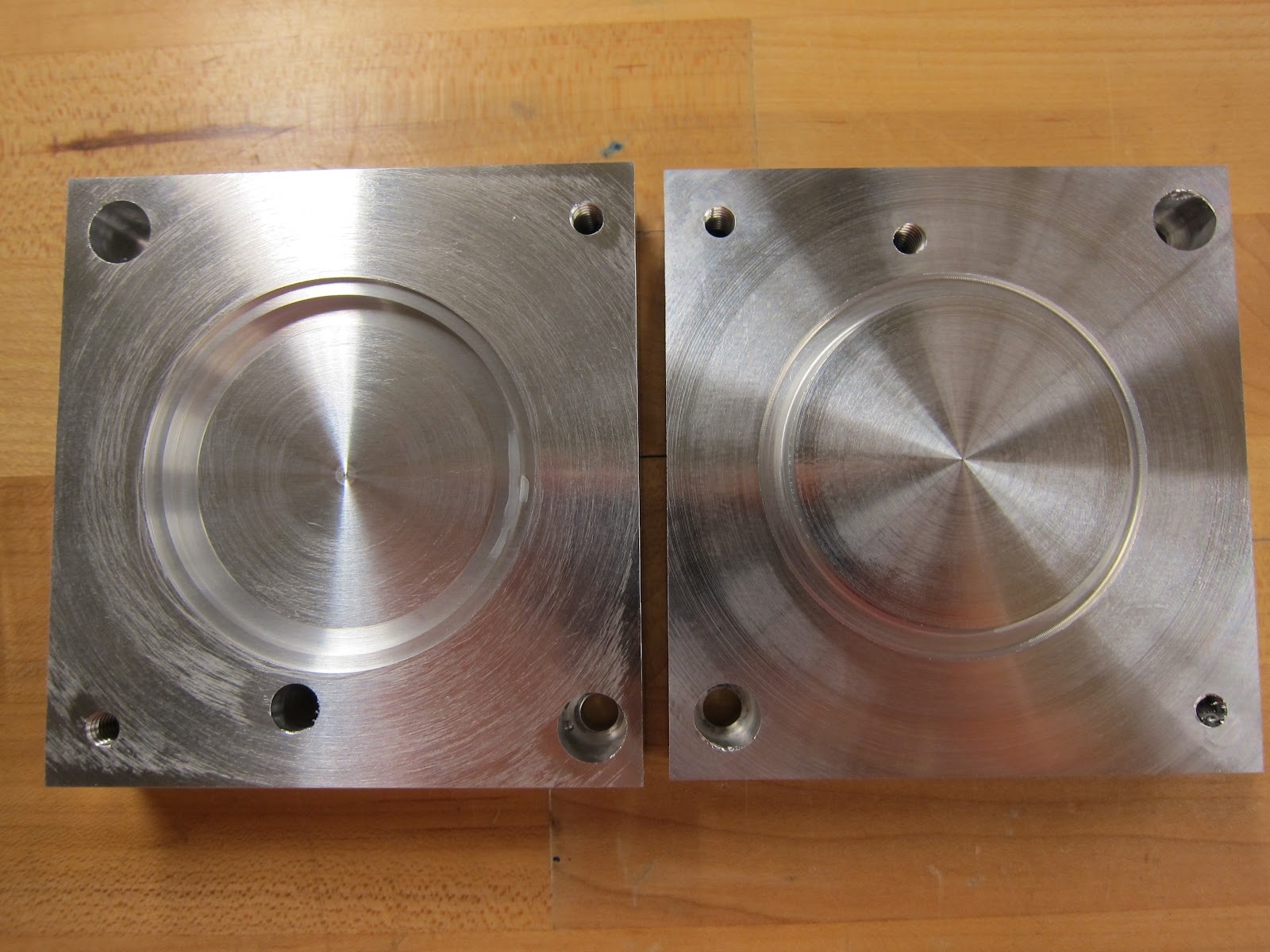

Body:


Key features:
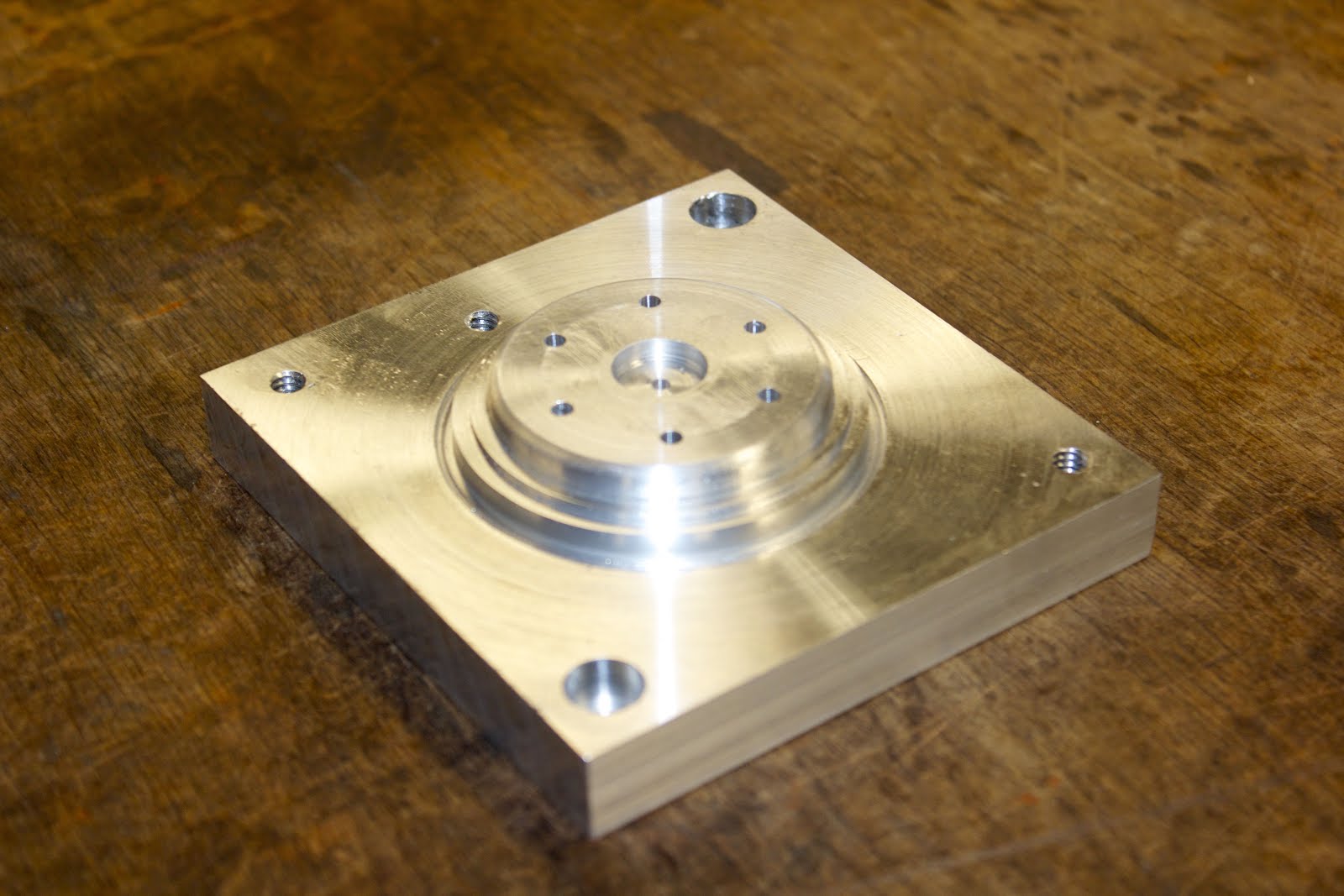
The body is actually formed from 3 molds, two cores and one cavity. This allows one side of the body to have a flat internal cavity, while the other body piece has a small plastic axle to spin the “wheel of fortune” disk. The body had to have a rounded exterior to slide past the string, while press-fitting to the ring and letterbox parts.

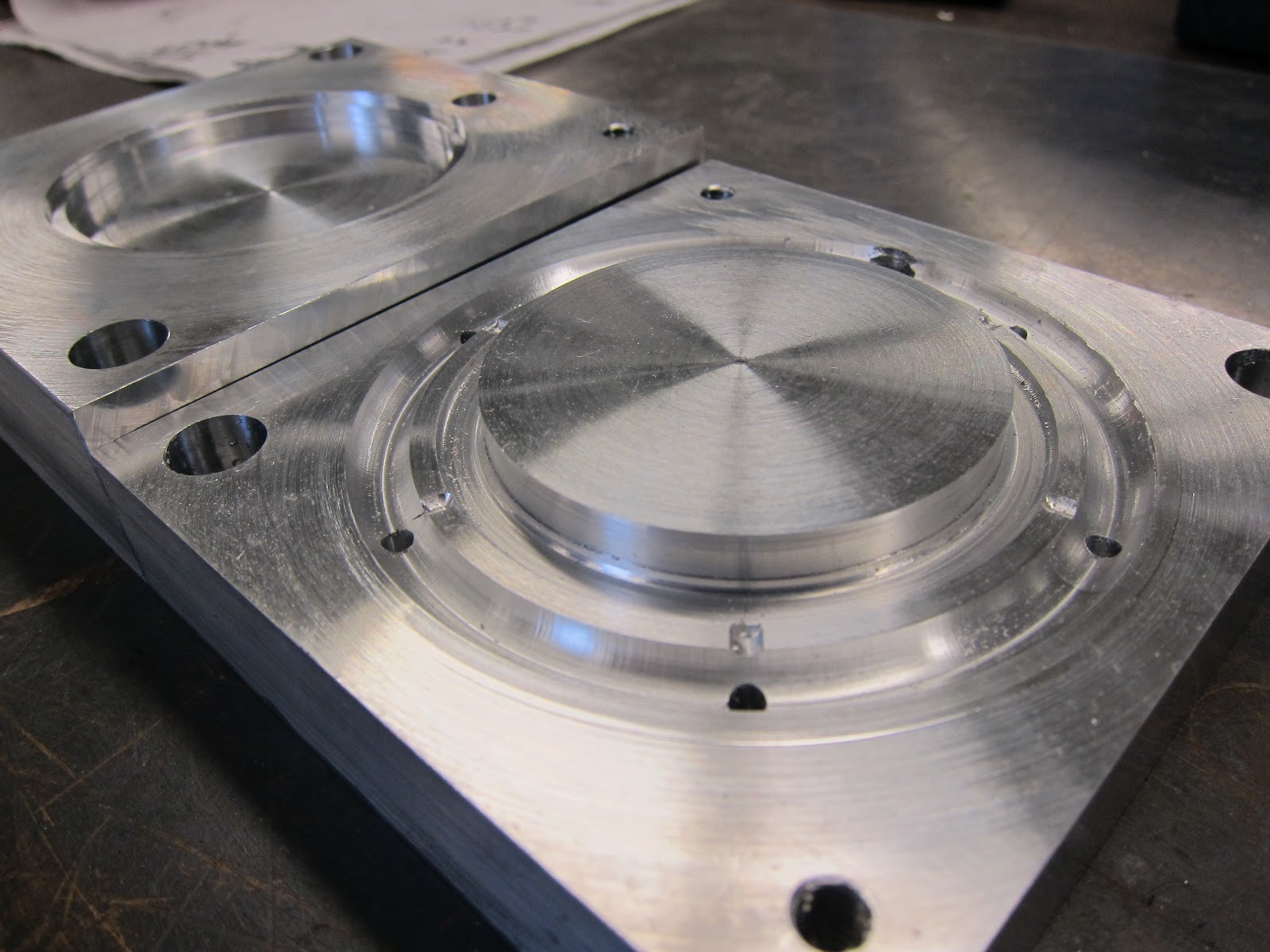
Here’s an image of one of the body core molds.


Successes:
The snap fits were remarkably consistent and did not require any remachining with the ring. I was also concerned about the spinner mount, because it was a long thin feature located far from the gate. Although the spinner mount was slightly rounded at the top, it was functional.


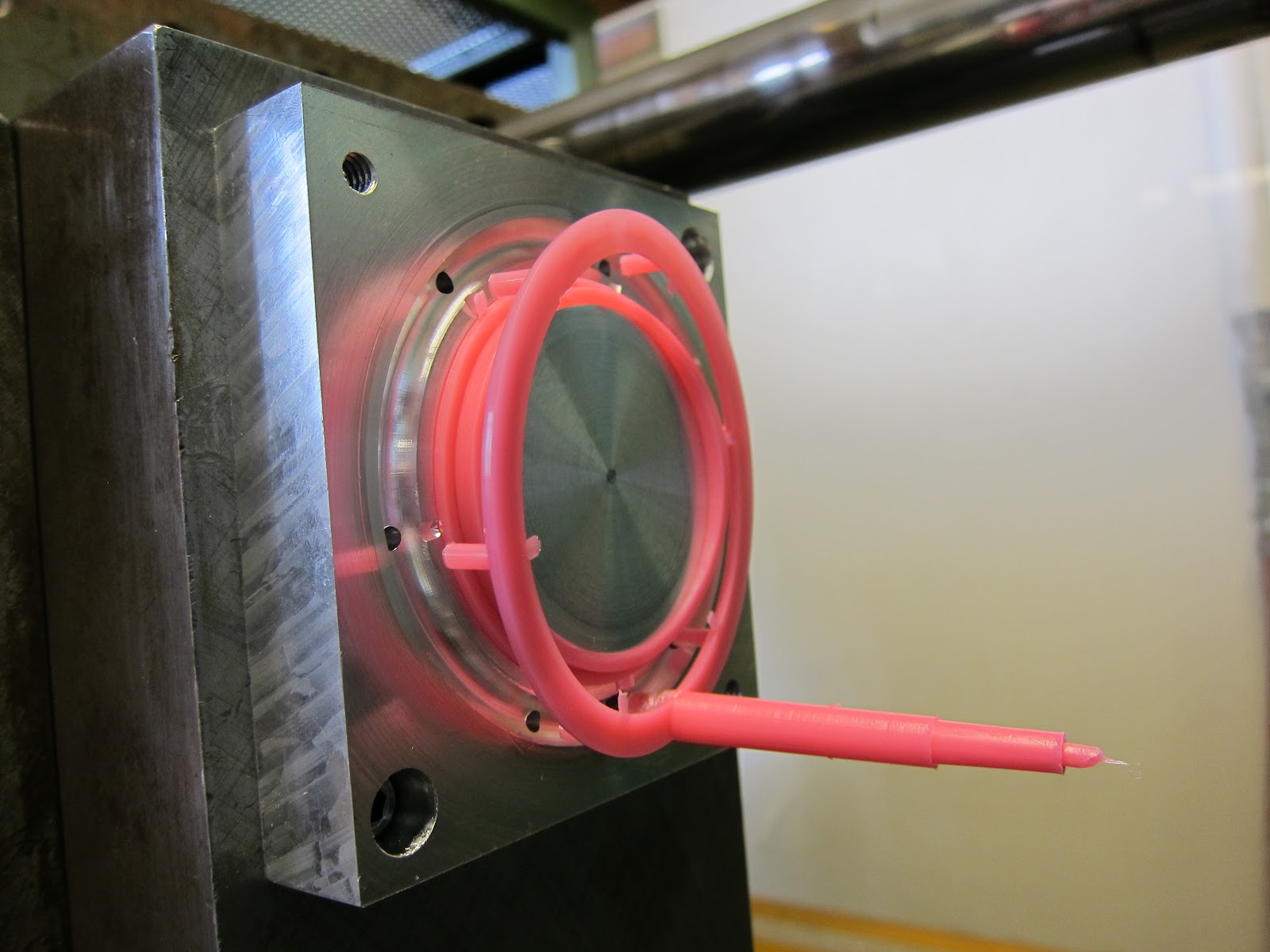
An early part, complete with flashing.

Opportunities for Improvement:


We encountered challenges with edges of the part, as plastic leaked out of the parting line during the cycle. The part is also large, and it didn’t cool completely before it was injected, leaving injector pin deformations. We solved these by increasing the clamping pressure and slightly reducing the shot volume. We also increased the cooling time, which reduced the ejector pin marks.

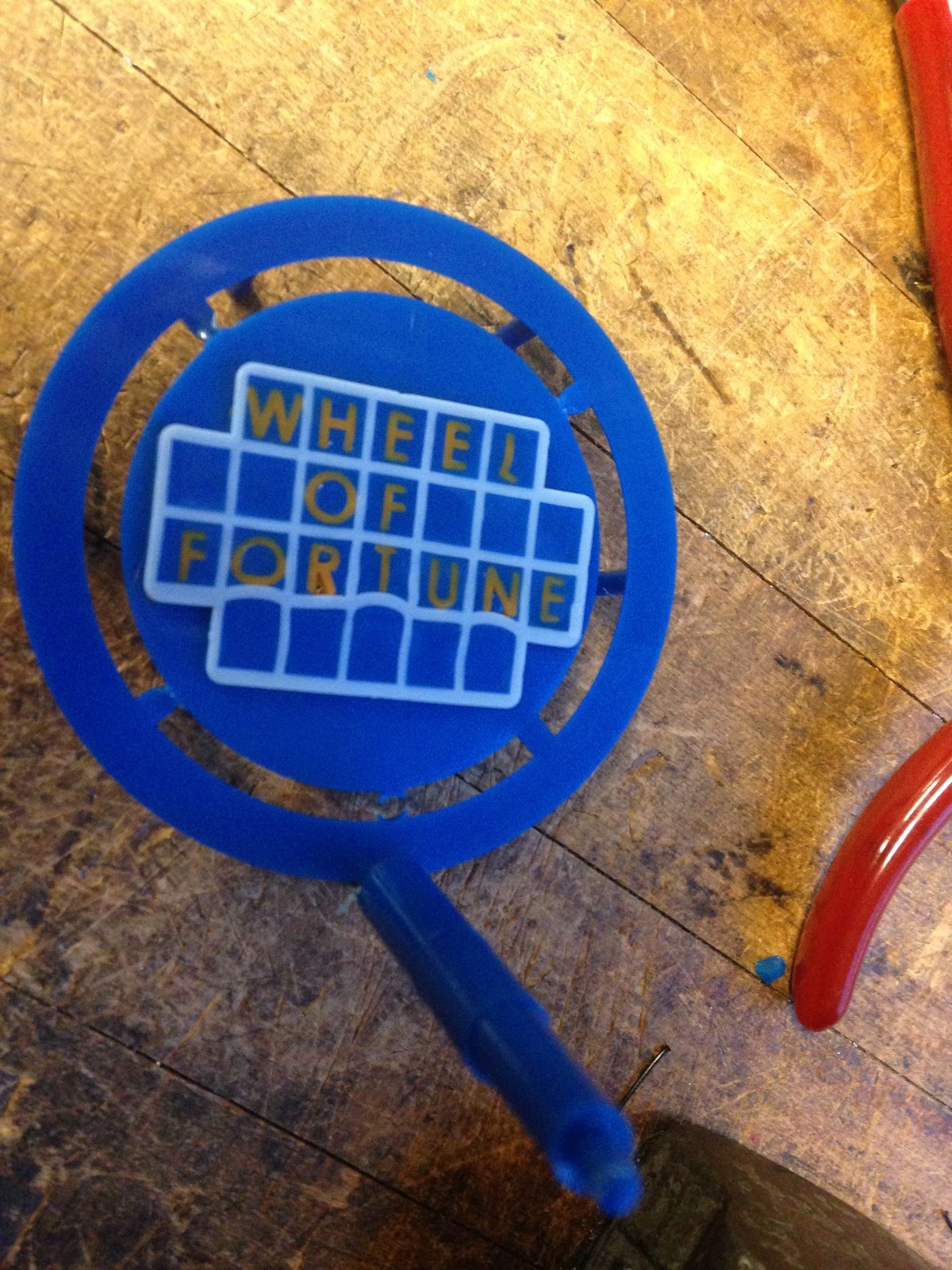
A body family tree, from first part to latest.


Table of specs comparing YY design specifications and measured specifications:


Thermoform Diameter
Design spec
2.100±0.005”
Measured spec
2.07942”
Explanation: There was no significant shrinkage in the measured spec of the thermoform - this could be because of small defects in machining or thin spreading of the plastic during thermoform. Overall, it was insignificant, and functionality was conserved.


Body with Spin Stick Snap Fit Diameter
Design spec
2.346±0.000/0.005”
Measured spec
2.29384”
Explanation: When injection molding, the parts produced by the mold shrink due to . Although we attempted to account for shrinkage by measuring previously injection molded parts, we were unable to completely predict the effects of shrinkages. However, the parts still snapfit together well, so functionality was conserved.


Body without Spin Stick Snap Fit Diameter


Design spec
2.346±0.000/0.005”
Measured spec
2.2908
Explanation: When injection molding, the parts produced by the mold . Although we attempted to account for shrinkage by measuring previously injection molded parts, we were unable to completely predict the effects of shrinkages. However, the parts still snapfit together well, so functionality was conserved. In addition, the body without spin stick had more shrinkage than the body with spin stick (as seen in the reduced measured spec) - this is because the spin stick acts to cool the body, resulting in less diameter shrinkage for the body diameter.


Retaining Ring Snap Fit Diameter
Design spec
2.3±0.005”/0.000
Measured spec
2.29933


Explanation: The retaining ring came out a little smaller than intended in the actual production run because injection molded parts shrink. This is due to the fact that the part contracts during cooling due to the part’s polymer properties. However, this was still okay because the body also shrunk during its production run.


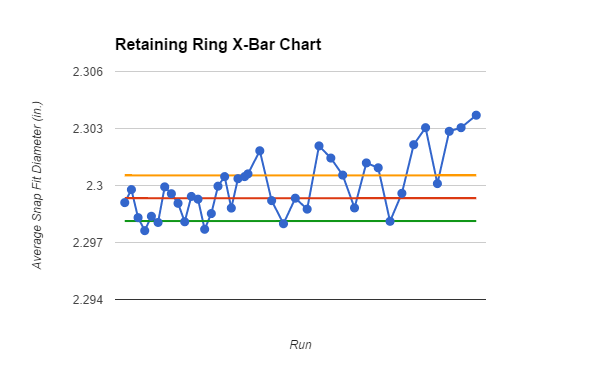
Summary of finding in Paper Deliverable 4 for retaining ring:
We chose the subgroup size to be five parts because it divides evenly into the 100 parts that were produced and is small enough to still provide a descriptive graph shape of the production:
Upper Control Limit  = 2.301 in.
Lower Control Limit = 2.298 in.
        The disturbance midway through the production run of the retaining ring did not produce a notable step change. For the disturbance, the pressures in the bottom row of the injection hold pressure profile were all dropped by 100 psi. It’s possible that the pressure change was too minor to produce a noticeable effect on the injection molded piece since the top half was still kept constant.
Process Capability:

Cp = = 6.672 x 10⁻⁶
Cpk = 16.18


According to this our process is not capable but 100 samples is also pretty low for understanding the process. With more optimization we and samples we could make this process more cabaple.


Here is the link to the paper deliverable.

Monday, November 17, 2014

Process Optimization: Retaining Ring


Since our last post of the Retainer Ring we have made a few modifications during the optimization process.

Changes to Mold

First Injection 

During the first injection (with the mold from the previous post) the ring had trouble ejecting from the mold. The small, plastic runners to the ejector pins would fold over with the force of the pins rather than push out the ring from the mold. 

Re-Machining 

To give better structural support to the ejector pin runners we added a thick plastic ring around our part and over each ejector pin. This gives better support because the ejector pins would have to bend all six runners in order to cause the same problem. This allowed for all the ejector pin force to used to eject the part 


Second Injection

During the second injection run the parts were ejecting well. No further changes to the mold are needed. 


Optimization Parameters 

Below are our injection molding parameters for this part. 


The cooling time was chosen because higher cooling times caused the part to shrink around the mold and get stuck to the core mold so well that we had to pry the part off with pliers. So the trade-offs for cooling time with our part is increased dimensional accuracy on the inner diameter versus forced need to get the part off the mold. 

The injection speed was set fairly high at first (the max injection speed on the 2.008 IM machine is 6.3) to make sure the entire ring was filled before freezing (cooling time is proportional to the feature's thickness squared thus our thin part could freeze before filling it all if we do not inject the plastic fast enough). 

The pressure profile is optimize to be the max pressure we can have with out flashing. 

Production Run

Last week we ran production on our retainer ring (and our yoyo body and thermoform cover!). Production ran smoothly for the most part (we had a bit of problem with flash at first but increased the clamping forces and lower the injection speeds reduced that significantly). 


Sunday, November 16, 2014

Process Optimization: Thermoform!

These past few weeks, we've been optimizing the thermoforming process.

Main Design Goals:
1. We wanted to reduce the webbing produced from the brass pins. With too much webbing, the thermoform piece won't fit flat underneath the retaining ring. When we cut the pieces, we wanted to have the outside of the ring be as flat as possible.
2. Reduce Thermoforming time (decrease cost)
3. Reduce Dust Specks (increase quality)

Iterations:
1. We started out with the default settings, but there was some webbing on the pins. We could also see a significant amount of dust specks on the mold.

2. We performed a few iterations to reduce the dust
- peeling the dust protector a few seconds before thermoforming
- cleaning off the plastic with compressed air
- wiping off the mold with a clean cloth. This method produced more significant results.

3. To reduce the amount of webbing, we decided to increase the heat time and increase the oven temperature. Increasing the oven temperature was also a good way to reduce thermoforming time.

4. After increasing heating time, we started to get a few problems where the piece would be deformed from being pulled off the mold. We decided that a longer cooling time was needed, so we increased the form time to allow for increased cooling before removing the plastic.


Notes from Production Run:
We made ~120 pieces in 2.5 hours. Despite optimization runs beforehand, we discovered during the production run that the machine became very warm. This resulted in a few problems, where the piece would be deformed from being pulled off the mold. As a result, we lowered the oven temperature to 640 F.

During the production run, we introduced a "glitch" in the run on purpose, in order to simulate different operating conditions. The glitch was a decrease in heating time to 200 seconds.


Thursday, October 23, 2014

STL Files

Here is a link to the STL files for our CAD.


https://drive.google.com/folderview?id=0BzH0B2Rs0kPGX2VSQWtEWDA4RmM&usp=sharing

Monday, October 20, 2014

Estimate Machining & Optimization Times

Last week we machined out first mold. Looking ahead, below are our expected machining times for all our molds. After machining our molds, we will begin injection molding and process optimizations and have included estimates for that below too. 


Machine Time Estimate for Lathe and Mill

Once our molds are made in Solidworks, we import them to Mastercam where we plan out what machines and tools we will use to make them. Mastercam is sync with the 2.008 Mill and CNC Lathe and thus gives us estimates for machining times on both machines. 
Part
Lathe Time
Mill Time
Yoyo Body Cavity
7 min 9 sec
0
Yoyo Body Core
6 min 29 sec
1 min 30 sec
YYB w/Spin Stick Core
6 min 29 sec
6 min 24 sec
Retaining Ring Core
2 min 39 sec
3 min 13 sec
Retaining Ring Cavity
35 sec
0
Thermoform
3 min 12 sec
54 seconds
Letter Mold Core
0
25 min
Letter Mold Cavity
0
1 hr 30 min
Gold Board Mold Core
0
30 min
Gold Board Mold Cavity
0
9 min 21 sec
Entire Wheel of fortune board Mold Core
1 min 1 sec
1 hr 5 min 27 sec**
Entire Wheel of fortune board Mold Cavity
3 min 37 sec
1 hr 16 min 40 sec**
**Has to be machined after letters and board have been injection molded to account for shrinkage before overmolding parts (more on overmolding later this week!)


Projected Timeline

Process Optimization
October 20th - November 10th
Make Final Parts
November 10th -November 24th
Assembly
November 24th - Dec 5th

Previously we planned on having all our molds made last week. However, due to longer machine times than expected and how quick machines get booked up, we have shifted our first injection molding iteration back by a week and will have to shorten our optimization and final production run time. (this is reflected also in our Gantt Chart).


Projected Process Optimization Time

To optimize our process we will run iterations of injection molding parts, measuring parts for accuracy, and re-designing as needed. To get an estimate of how long this process will take we have estimated the time of these iterations. 

Injection Molding time is dominated by cooling time. From class lecture, we learned that cooling time can take upwards of half of the entire injection molding process. Cooling time for our parts can be derived from the equation Cooling Time=(thickness of part)^2/alpha, where alpha is the thermal diffusivity of the material. Our yoyos will be made from polypropylene with a thermal diffusivity of 0.096mm^2/s. Our parts have an average thickness of ~2.54mm, thus the average cooling time is about 67 seconds. To make 10 parts will thus take us about 20 minutes. For all our parts it will take us ~110 minutes (we have already booked 3 hours of IM time so we'll have our first iteration of all parts done this week!). Thermoforming each part also takes us about a minute, adding 20 minutes to our total estimate.

At worse we expect to have to re-machine all our molds and injections mold again. Our total machine time is about 5.5 hours. So our total process optimization time is roughly 16 hours of lab time plus the time to re-CAD any changes. We believe 3 weeks should be sufficient time to get this done between the five of us.